Pipeline: Frequent VLA problems
General Description
The VLA pipeline delivers calibrated data and some initial images of VLA observation runs. The quality of the calibration and imaging products is usually assessed through the weblog that is created in each pipeline run (see also the VLA Pipeline guide). During the observations, the VLA may have encountered technical problems that are reflected in various ways in the weblog, where graphs show the behavior of the calibration tables as a function of time, frequency, polarization, etc., and analytical numbers describe the amount of flagging, derived fluxes, image statistics, etc.
Here we would like to briefly describe common VLA observing problems, how they are identified in the pipeline calibration weblog, and how they can be addressed.
Pointing
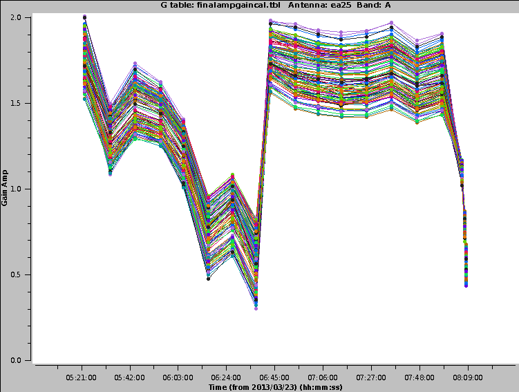
At higher frequencies the VLA requires regular pointing calibrations. Each pointing run will reposition the antennas to be centered on a strong source. If the pointing solution fails, the amplitude of the source will drop. A typical graph looks like the one shown in Fig. 1. The pointing solution for the first half of the run failed, which results in the source drifting away from the center of the primary beam. After a pointing update in the middle of the run, the antenna is positioned properly again.
 |
FIX: If the pointing is only off by a small amount, the gain calibration will take care of it. If it is off by a large amount, the data for this period and antenna needs to be flagged.
RFI
Deformatter Problems
The digital transmission system (DTS) of each VLA antenna includes a formatting stage to convert the electronic to an optical signal before it is injected on the optical fiber link. On the correlator end the signal will be deformatted back to an electronic signal. Occasionally, the timing on the deformatter can be misaligned which results in very strong amplitude or phase slopes as a function of frequency. Sometimes the signal is similar to an abs(sin), or a 'bouncing' signal across a baseband for one polarization. The stage 6 tries to identify such deformatter errors by checking for deviations more than 15% over the average bandpass. If more than 4 spws of a baseband are affected this way, the entire baseband will be flagged.
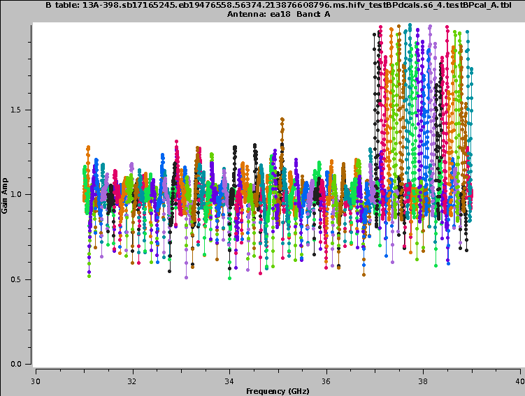
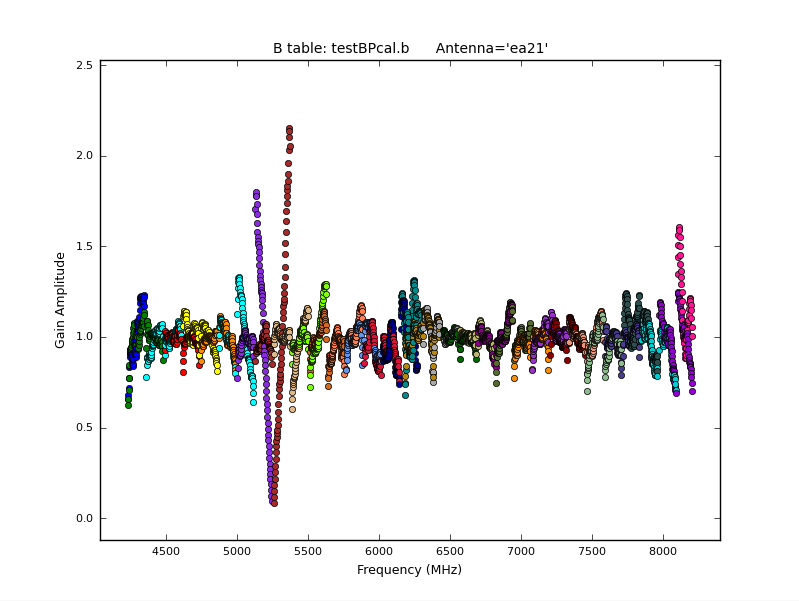
For our data, no deformatter issues were automatically detected in the data (see the tables in the bottom of the main page (Fig. 15, bottom). We did see, however, that ea18 has a DTS problem in the 37-39GHz baseband (Figs. 19b/21a and 20c). Since this stage 6 did not detect and flag this range (which shows the limitations of the underlying code), manual flagging will be required for the affected antenna, polarization, and baseband for all sources. An example from a different dataset is provided in Fig. 21b. The 'V' shape close to 5.3 GHz with some values reaching close to zero are a sign for a deformatter problem.
 |
 |