Pipeline: Frequent VLA problems
General Description
The VLA pipeline delivers calibrated data and some initial images of VLA observation runs. The quality of the calibration and imaging products is usually assessed through the weblog that is created in each pipeline run (see also the VLA Pipeline guide). During the observations, the VLA may have encountered technical problems that are reflected in various ways in the weblog, where graphs show the behavior of the calibration tables as a function of time, frequency, polarization, etc., and analytical numbers describe the amount of flagging, derived fluxes, image statistics, etc.
Here we would like to briefly describe common VLA observing problems, how they are identified in the pipeline calibration weblog, and how they can be addressed.
Radio Frequency Interference
By far the biggest problem is radio frequency interference (RFI). RFI is produced by internal and external sources, can be terrestrial or from satellites that operate at or spill into the observed frequency. For the VLA, please find more information on the Radio Frequency Interference webpage. Although weak RFI may only slightly raise the noise of an image, stronger RFI will produce artifacts that may render the data unusable. An example for strong RFI is shown below. Flagging procedures are outlined in the VLA topical CASA guide on flagging.
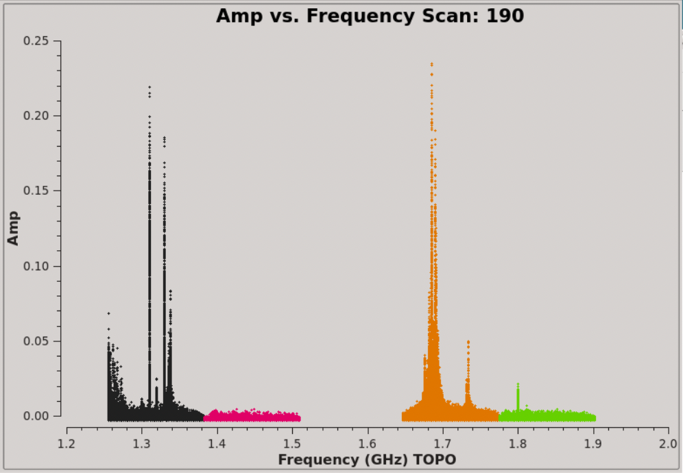 |
FIX: Weak, intermitted RFI will increase the noise and down-weighted in the imaging in the hifv_statwt task. Strong RFI needs to be flagged and only clean data should be calibrated and imaged. Flagging can be manual or automatic.
Pointing
At higher frequencies the VLA requires regular pointing calibrations. Each pointing run will reposition the antennas to be centered on a strong source with known position. If the pointing solution fails, the amplitude of the source will drop. A typical graph looks like the one shown below. The pointing solution for the first half of the run failed, which results in the source drifting away from the center of the primary beam. After a pointing update in the middle of the run, the antenna is positioned properly again (the very last data points are actually a different source, hence the drop at the edge).
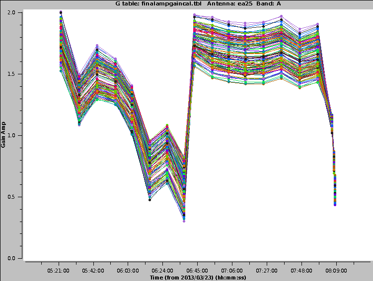 |
FIX: If the pointing is only off by a small amount, the gain calibration will take care of it. If it is off by a large amount, the data for this period and antenna needs to be flagged.
DTS/Deformatter Problems
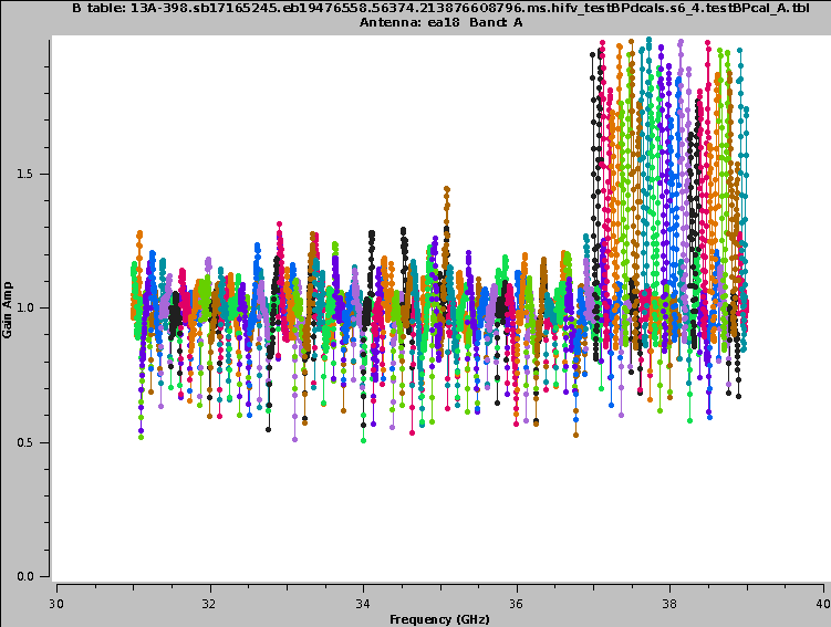
The digital transmission system (DTS) of each VLA antenna includes a formatting stage to convert the electronic to an optical signal before it is injected on the optical fiber link. On the correlator end the signal will be deformatted back to an electronic signal. Occasionally, the timing on the deformatter can be misaligned which results in very strong amplitude or phase slopes as a function of frequency. Frequently the signal is similar to an abs(sin), or a 'bouncing' signal across a baseband for one polarization, or, in other terms, various numbers of 'V' shapes in the data.
 |
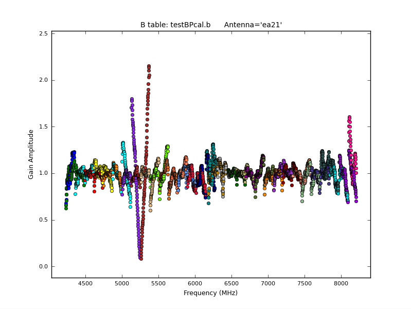 |
FIX: The data in for this baseband, antenna and polarization needs to be flagged.
Correlator Zeros
Under some circumstances, the WIDAR correlator writes exact zeros. The pipeline will usually flag them automatically. If not, they can be removed with CASA"s flagdata task, using the option mode='clip' with clipzeros=True or flag the zeros by hand.
FIX: The pipeline will usually catch them. If not, use CASA's flagdata task.
Baseband and Subband Edges
If spw roll-off frequency edges are very steep, they can degrade gain and phase solutions. Frequently this is not a big problem, but if the gain for the edge channels is close to zero, a division by the bandpass for these channels can get extremely noisy. this is [particularly true for baseband edges. The edgespw, fracspw, and baseband parameters in hifv_flagdata can be adjusted to flag different percentages of the edges (see also VLA pipeline pages). Surely, the edges can also be flagged with the CASA task flagdata, or by hand.
FIX: Adjust the relevant parameters in hifv_flagdata and re-run the pipeline.
Compression
Strong RFI can bring the the digital and analog receiver system into a non-linear regime (also known as compression). Simple RFI flagging alone will not be sufficient to remove compression. The affected antennas/spw/pols will likely need to be flagged. Some compression can be corrected by a script.
FIX: For strong compression, flag the affected data. Weak compression may increase the Tsys.
Resolved Calibrators
Some calibrator sources are not perfect point sources. For the VLA standard flux calibrator sources, models are provided within CASA. For resolved phase calibrators, the uv-range can be restricted during the solve for the calibration tables.
FIX: Restrict the uv-range for the calculations of the calibration tables.
Wrong Intents
If the intents of the data are set incorrectly for the observations, the pipeline will use the wrong calibrators for the calibration. Usually this can be fixed by overwriting the intents. The VLA pipeline webpage provides instructions and a script to do this. For more complicated setups, like multiple calibrators or bands with separate calibrator scans, data may be split into smaller MSs that contain only the relevant calibrators for each target, or data reduction by hand may be needed.
Non-ideal reference antenna
Sometimes, if the reference antenna has some issue, like RFI or extreme flagging, it is advisable to switch to a different reference. Use the 'refantignore' keyword to disallow the use of this antenna as a reference. The Pipeline Page provides details on the usage of this keyword.
FIX: Use 'refantignore' to remove the a problematic antenna from the list of possible reference antennas.
Extreme Solution Intervals
If the hifv_solint stage shows extreme values for the short and/or long solution intervals, then the data should be inspected and flagged.
FIX: Flagging bad data.
Weather
Weather can be good or bad. Bad weather can introduce extreme phase jumps, large increase in Tsys, or pointing errors. Flagging times during bad weather may help. The CASA task statwt will down-weight some noise variations. Also selfcal (Topical Guide: VLA Self-calibration Tutorial) will correct for phase variations. In extreme cases, however, flagging is the only method.
For some SBs the weather data are missing from the header. This is usually not a big problem. The data can be filled, however, on request. Please contact the NRAO helpdesk.
FIX: Statwt, selfcal, or flagging.
Decorrelation
The pipeline will correct for some degree of decorrelation for all calibrators. In extreme cases data need to be flagged though. If decorrelation is strong. It can be assumed that the target also shows significant decorrelation. Self-calibration will be advised if the source flux is sufficient. A CASA guide for self-calibration is provided: Topical Guide: VLA Self-calibration Tutorial.
FIX: Self-calibration. in extreme cases: flagging.
Shadowing
The pipeline flags shadowed antennas by default. If not all of shadowing is captured, or if the shadowing criteria shall be loosened (e.g. allow a small amount of shadowing), then this can be controlled by the CASA task flagdata 'mode='shadow'. After manually flagging the data, he 'hifv_flagdata' task call should then be modified ('shadow=False') to not do additional shadowing flagging.
FIX: in CASA: flagdata mode='shadow'
Switches
FIX:
Phase Jumps
Various hardware failures can cause the phase for a given antenna to be unstable in time, often with sudden, large changes in phase in time. Depending on where the problem is, this may affect just a portion of the data to all data on a given antenna. In the first example below, only one baseband's data is affected (large changes at each data point) while the other baseband remains near zero and is not affected. This plot, from the pipeline's Final phase gain cal section found in the hifv_finalcals stage, shows the final phase solutions found for each calibrator (using the long solution interval).
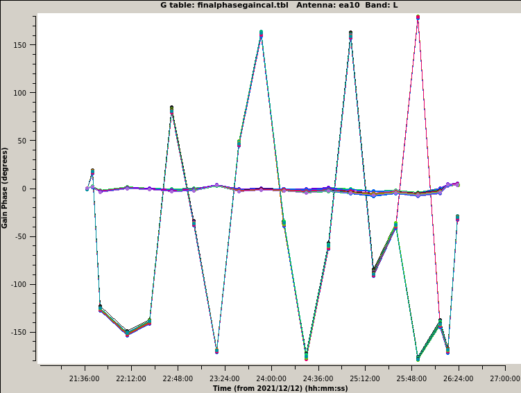 |
FIX: If there are phase jumps, usually the data for the affected time range needs to be flagged for that antenna(s).