Imaging M99: Difference between revisions
No edit summary |
No edit summary |
||
| Line 47: | Line 47: | ||
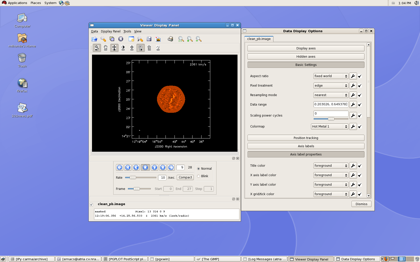
[[Image:m99cube.png | thumb| viewer display on the desktop, with accompanying Data Display options GUI.]] | [[Image:m99cube.png | thumb| viewer display on the desktop, with accompanying Data Display options GUI.]] | ||
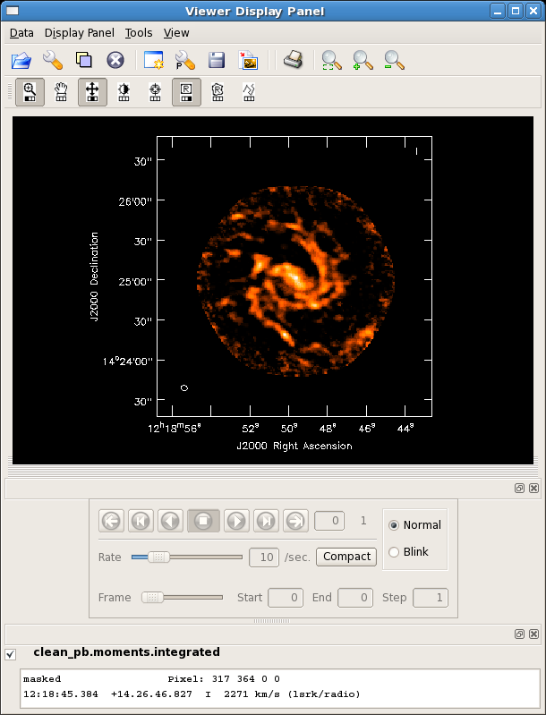
[[Image:m99mom0.png| thumb| moments=[0] map of NGC4254]] | |||
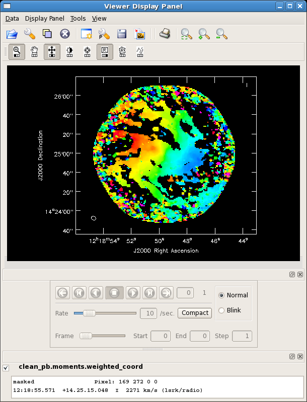
[[Image:m99mom1.png| thumb| moments=[1] map of NGC4254]] | |||
In addition to basic file selection commands, the upper part of the Viewer Display Panel includes various image display tasks (e.g, zoom, rectangle region select, contrast) that can be assigned to different mouse buttons by clicking on them with the desired mouse button. The lower part of the Viewer Display Panel provides buttons which allow you to navigate between spectral channels, and the coordinate and flux information of the pixel under the cursor is displayed at the bottom of this window. The Data Display Options window (which appears after selecting 'Data' > 'Adjust' from the top menu bar) allows you to adjust the data range for the color scale as well as a number of plotting options (e.g., whether information about the third dimension of the cube is displayed in the upper right corner, and in what units.) | In addition to basic file selection commands, the upper part of the Viewer Display Panel includes various image display tasks (e.g, zoom, rectangle region select, contrast) that can be assigned to different mouse buttons by clicking on them with the desired mouse button. The lower part of the Viewer Display Panel provides buttons which allow you to navigate between spectral channels, and the coordinate and flux information of the pixel under the cursor is displayed at the bottom of this window. The Data Display Options window (which appears after selecting 'Data' > 'Adjust' from the top menu bar) allows you to adjust the data range for the color scale as well as a number of plotting options (e.g., whether information about the third dimension of the cube is displayed in the upper right corner, and in what units.) | ||
| Line 59: | Line 61: | ||
The above command will create two output images: a zero moment map (moments=[0,... ,'clean_pb.moments.integrated') and a first moment map (moments=...,1], 'clean_pb.moments.weighted_coord'). It will include all pixels in each velocity channel which have flux densities above -100 Jy and below 75mJy (about 3 sigma). As is typical for creating integrated intensity and velocity field maps in this way, a higher cutoff is desirable for the moment 1 map; this can be seen by looking at the output moment 1 map (*.weighted_coord). It may be desirable to run [[immoments]] multiple times with different inputs to create each moment image. The task [[immoments]] also allows the user to specify a mask, select a subset of channels, or a region defined with the viewer, if more control is desired over the data to be used in the moment calculations. | The above command will create two output images: a zero moment map (moments=[0,... ,'clean_pb.moments.integrated') and a first moment map (moments=...,1], 'clean_pb.moments.weighted_coord'). It will include all pixels in each velocity channel which have flux densities above -100 Jy and below 75mJy (about 3 sigma). As is typical for creating integrated intensity and velocity field maps in this way, a higher cutoff is desirable for the moment 1 map; this can be seen by looking at the output moment 1 map (*.weighted_coord). It may be desirable to run [[immoments]] multiple times with different inputs to create each moment image. The task [[immoments]] also allows the user to specify a mask, select a subset of channels, or a region defined with the viewer, if more control is desired over the data to be used in the moment calculations. | ||
[[CARMA Tutorials | ↵ '''CARMA Tutorials''']] <br> | [[CARMA Tutorials | ↵ '''CARMA Tutorials''']] <br> | ||
[[Main Page | ↵ '''CASAguides''']] | [[Main Page | ↵ '''CASAguides''']] | ||
Revision as of 17:22, 29 April 2010
This part of the tutorial shows an example of creating an image and a zeroth moment map of NGC4254 (M99), using the example track taken by CARMA STING.
As before, this example assumes that you have made the following global definitions in CASA:
# In CASA
msdir='./'
project='c0104I'
msfile=msdir+project+'.ms'
If your visibility data are already edited and calibrated, there's really only one step left to get you to an image: clean. Unlike in MIRIAD, which has separate tasks for inverting and cleaning an image, CASA does it in one step. If you want a dirty image, just set niter=0 so that clean doesn't actually do any...cleaning.
Here's a command-line call to clean, which demonstrates many of the interesting parameters you can tweak. This is a simple example, assuming you are making an image of the entire mosaic, and you want to clean the whole thing.
Some things of note (input parameters are italicized):
- phasecenter doesn't need to be specified, if you are happy with the phase center at the position of the first of the observed source fields. Otherwise, you can specify an RA and dec, e.g., phasecenter='J2000 12h12m12.00 12d12m12.00', or a field number, as shown in the example below.
- it is important for both imagermode and ftmachine to be set to 'mosaic' if you want your mosaicked data to be stitched together correctly (this should happen by default).
- the parameters pbcor and minpb set whether or not a primary beam correction is done, and how far out, respectively.
- always include units when specifying the threshold at which to stop cleaning.
This command produces a naturally-weighted image 512x512 arcsec in angular size, which has been cleaned down to a threshold of 50mJy (about 2 sigma) and has been primary-beam corrected (see 'minpb' and 'pbcor'):
# In CASA
clean(vis=msfile,imagename='clean_pb',spw='1~2',field='NGC4254',
      phasecenter='11',
      cell=1.,imsize=[512,512],
      mode='velocity',start='2271km/s',width='10.0km/s',nchan=28,
      interpolation='nearest',psfmode='clark',
      imagermode='mosaic',ftmachine='mosaic',
      scaletype='SAULT',restfreq='115.2712GHz',interactive=F,
      minpb=0.2,pbcor=True,
      niter=5000,threshold='50mJy',mosweight=False,
      weighting='natural')
To take a look at the image you produced, use the CASA viewer:
# In CASA
viewer(infile='clean_pb.image')


In addition to basic file selection commands, the upper part of the Viewer Display Panel includes various image display tasks (e.g, zoom, rectangle region select, contrast) that can be assigned to different mouse buttons by clicking on them with the desired mouse button. The lower part of the Viewer Display Panel provides buttons which allow you to navigate between spectral channels, and the coordinate and flux information of the pixel under the cursor is displayed at the bottom of this window. The Data Display Options window (which appears after selecting 'Data' > 'Adjust' from the top menu bar) allows you to adjust the data range for the color scale as well as a number of plotting options (e.g., whether information about the third dimension of the cube is displayed in the upper right corner, and in what units.)
To create moment maps of this data cube, use the task immoments:
immoments(imagename='clean_pb.image',moments=[0,1],axis='spectral',
          excludepix=[-100,0.075],outfile='clean_pb.moments')
The above command will create two output images: a zero moment map (moments=[0,... ,'clean_pb.moments.integrated') and a first moment map (moments=...,1], 'clean_pb.moments.weighted_coord'). It will include all pixels in each velocity channel which have flux densities above -100 Jy and below 75mJy (about 3 sigma). As is typical for creating integrated intensity and velocity field maps in this way, a higher cutoff is desirable for the moment 1 map; this can be seen by looking at the output moment 1 map (*.weighted_coord). It may be desirable to run immoments multiple times with different inputs to create each moment image. The task immoments also allows the user to specify a mask, select a subset of channels, or a region defined with the viewer, if more control is desired over the data to be used in the moment calculations.