OT tutorial SISS 2018: Difference between revisions
No edit summary |
|||
| Line 25: | Line 25: | ||
Before starting to craft a proposal, you should have an estimate of some characteristics of your source (or at least estimates). These include (but are not limited to): | Before starting to craft a proposal, you should have an estimate of some characteristics of your source (or at least estimates). These include (but are not limited to): | ||
* The coordinates of the source(s) | * The coordinates of the source(s) and its velocity towards the observer (in km/s or redshift) | ||
* The extent or size of the emission/absorption regions | * The extent or size of the emission/absorption regions, which will inform your necessary spatial resolution, as well as your largest angular scale (in arcseconds) | ||
* If it is an emission/absorption line experiment, the width of the frequency structure that you want to detect (in km/s or kHz/MHz/GHz) | * If it is an emission/absorption line experiment, the width of the frequency structure that you want to detect (in km/s or kHz/MHz/GHz) | ||
* Its continuum emission flux, based on your own models or previous observations (in Jy/beam at a given frequency) | * Its continuum emission flux, based on your own models or previous observations (in Jy/beam at a given frequency) | ||
Revision as of 18:30, 3 May 2018
The objective of this tutorial is to describe the key observational parameters which you would need to define to propose for ALMA observations (spatial resolution, sensitivity, spectral setup), and to let you play with the ALMA OT so that you feel comfortable enough to craft your own proposal for the next Call for Proposals (next spring!).
We will first work through the M100 example proposal from the ALMA Primer (the Cycle 6 version is here). Afterwards, you can work through another Primer example of your choice, or start a proposal based on your own science.
Note that many special modes are not described in this basic tutorial. We recommend the OT User Manual for further reference.
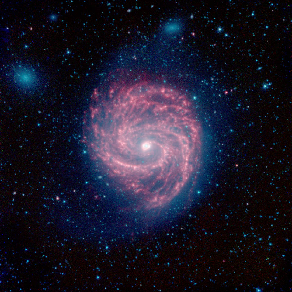
Primer example: Mosaic of the spiral galaxy M100
<figure id="M100_NASA.jpg">
</figure>
Science Aim: Map the distribution and kinematics of molecular gas in a nearby spiral galaxy
M100 (NGC 4321) is a bright, fairly face-on spiral galaxy in the Virgo Cluster. As one of the nearest spiral galaxies with well-defined arms and active star formation, M100 has been studied at virtually every wavelength, including the millimeter. These studies reveal a rich molecular interstellar medium (ISM) fuelling the star formation visible at optical and IR wavelengths. A bar funnels gas to the center of M100, leading to a nuclear concentration of molecular gas and star formation while fainter molecular emission traces the spiral arms.
ALMA imaged M100 as a science verification target and the data are available from the Science Portal. Tomorrow you may choose to work through an ALMA casaguide on combining data from the 12-m Array, the 7-m Array, and the TP Array (see here).
ALMA’s excellent imaging fidelity, mosaicing capabilities, and sensitivity to large angular scale (via the ACA) make a wide-field, high-resolution image of a galaxy like M100 a viable project. Such data would probe the dynamical effects of spiral arms and the nuclear bar on molecular gas, map the density distribution of the molecular ISM, and allow comparisons of molecular material to the distributions of dust, recent star formation, stellar populations, and other phases of the ISM.
Source characteristics
Before starting to craft a proposal, you should have an estimate of some characteristics of your source (or at least estimates). These include (but are not limited to):
- The coordinates of the source(s) and its velocity towards the observer (in km/s or redshift)
- The extent or size of the emission/absorption regions, which will inform your necessary spatial resolution, as well as your largest angular scale (in arcseconds)
- If it is an emission/absorption line experiment, the width of the frequency structure that you want to detect (in km/s or kHz/MHz/GHz)
- Its continuum emission flux, based on your own models or previous observations (in Jy/beam at a given frequency)
- A list of transitions (lines) of interest observable with ALMA which are present (or expected to be) in the source, and their estimated brightness (in Jy/beam). You can use the Splatalogue to determine which lines of interest are encompassed within the ALMA bands. Be careful to include the sources' redshift/velocity when you do your line search.
We'll go over each of these for M100:
Source coordinates and kinematic information:
- R.A. 12:22:54.8989, Decl. 15:49:20.570
- Distance: 16 Mpc
- Heliocentric velocity = 1569.779 km/s
- z = 0.00525
Source size (how large an area do we want to image?):
To capture the main spiral arms of M100, we will need to map an area ~270" on a side. This is much larger than the ALMA primary beam at Band 3 (see below), and will require a mosaic.
Do we want to observe continuum emission, or line emission? At what frequency?
We want to observer the molecular gas associated with this spiral galaxy, so we will propose to observe CO 1-0 emission in Band 3.
What angular resolution do we need?
2” is ~ 150 pc at the distance of M100. This doesn’t quite resolve individual Giant Molecular Clouds at this distance, but will certainly resolve the spiral arms, bar, and large molecular complexes.
What is the largest angular scale of the emission?
M100 exhibits structure over a large range of spatial scales. We will let the Largest Angular Scale to be the size of the map, 270", to recover the emission structure at all scales down to the resolution of the observations. As you will see, this will trigger observations with the 12m array, the 7m array, and the total power array.
What sensitivity (over what channel width) do we need for these observations?
Large molecular clouds like the Orion complex have masses ~5 x 10⁵ MSun or more. We design the survey of M100 to detect these kinds of clouds. For a CO-to-H2 conversion factor of ~2x1020 cm-2 (K km/s)-1 and assuming a CO line width of 10 km/s, a 1σ sensitivity of 3 mJy/beam corresponds to a 1σ molecular mass sensitivity of 8 x 10⁴ MSun per beam per 10 km/s channel, enough to detect Orion-like clouds at S/N ~ 5 or more.
Measurement goals
Now that you know a little more about your source(s), you should decide what measurements would allow you to meet the scientific goals which you want to achieve. Of course, the measurements must be achievable within the capabilities offered by ALMA. Cycle 6 capabilities are listed here.
In general, you should in particular decide:
- The spatial resolution do you want to reach
- The signal to noise do you want to achieve (on a line detection or on the continuum detection)
- The frequency range(s) which you want to observe.
- For continuum observations, the choice of frequency is usually driven by the optimal compromise between signal to noise and spatial resolution. You can play with the continuum reference frequency in the OT to determine which is the best option depending on your goal.
- For line observations, this choice is driven by the sky frequencies of the lines would be the most suited for your scientific goal (based on your own models, previous publications, line parameters from Splatalogue)
- The maximal spatial scale which you want to be able to retrieve
It is very likely that you will need to go back and forth and modify your original goals while preparing the proposal, to satisfy constraints on ALMA observational setups, or optimize the signal to noise.
For M100, we want to map a relatively large area in the emission from CO 1-0 in Band 3 with 2" angular resolution. Our sensitivity needs are described above.
<figure id="OT_blank.png">
</figure>
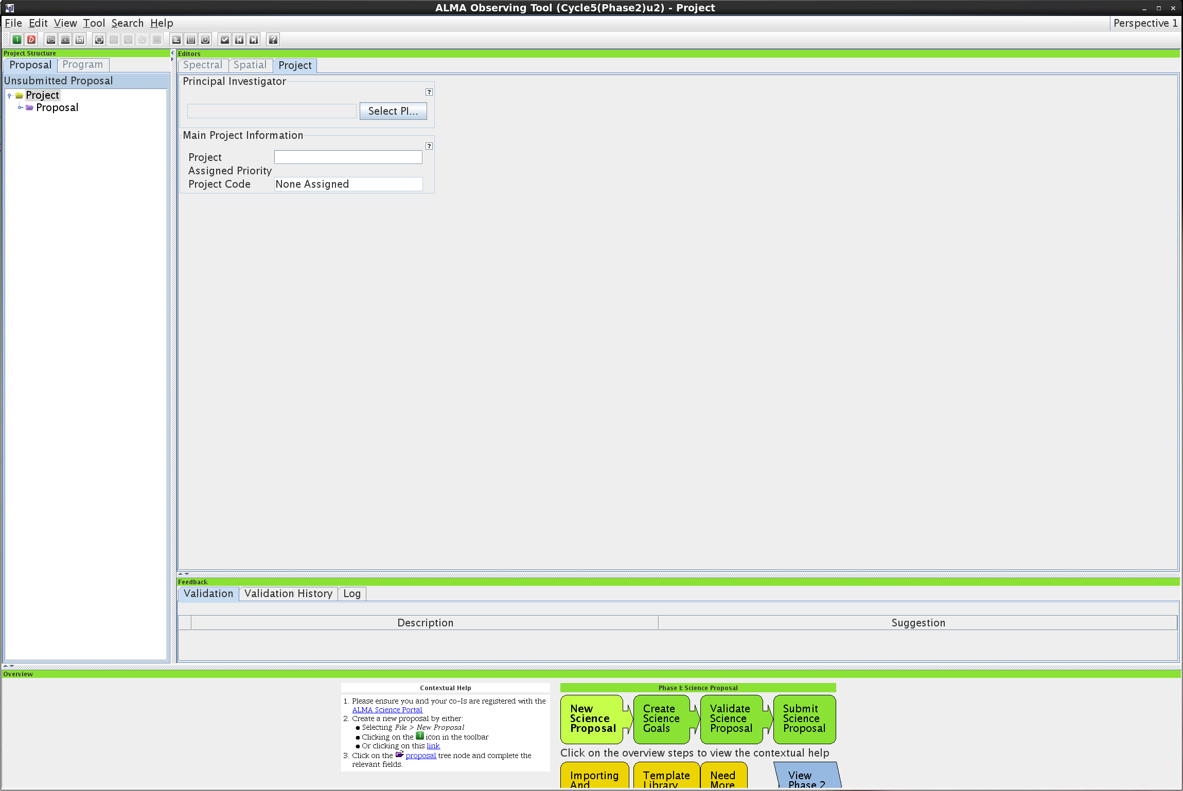
Starting your proposal in the OT
With your science goals and calculations above, it's now time to open the OT to prepare your proposal. At home, you would need to download the OT from the ALMA portal. Here, we've already installed the OT on your computer.
<figure id="OT_PIselect.png">
</figure>
- type ALMA-OT.sh in a terminal
- select 'Create a new proposal' in the pop-up window. You will see a tree structure on the left panel of the OT display, which describes the structure of the proposal.
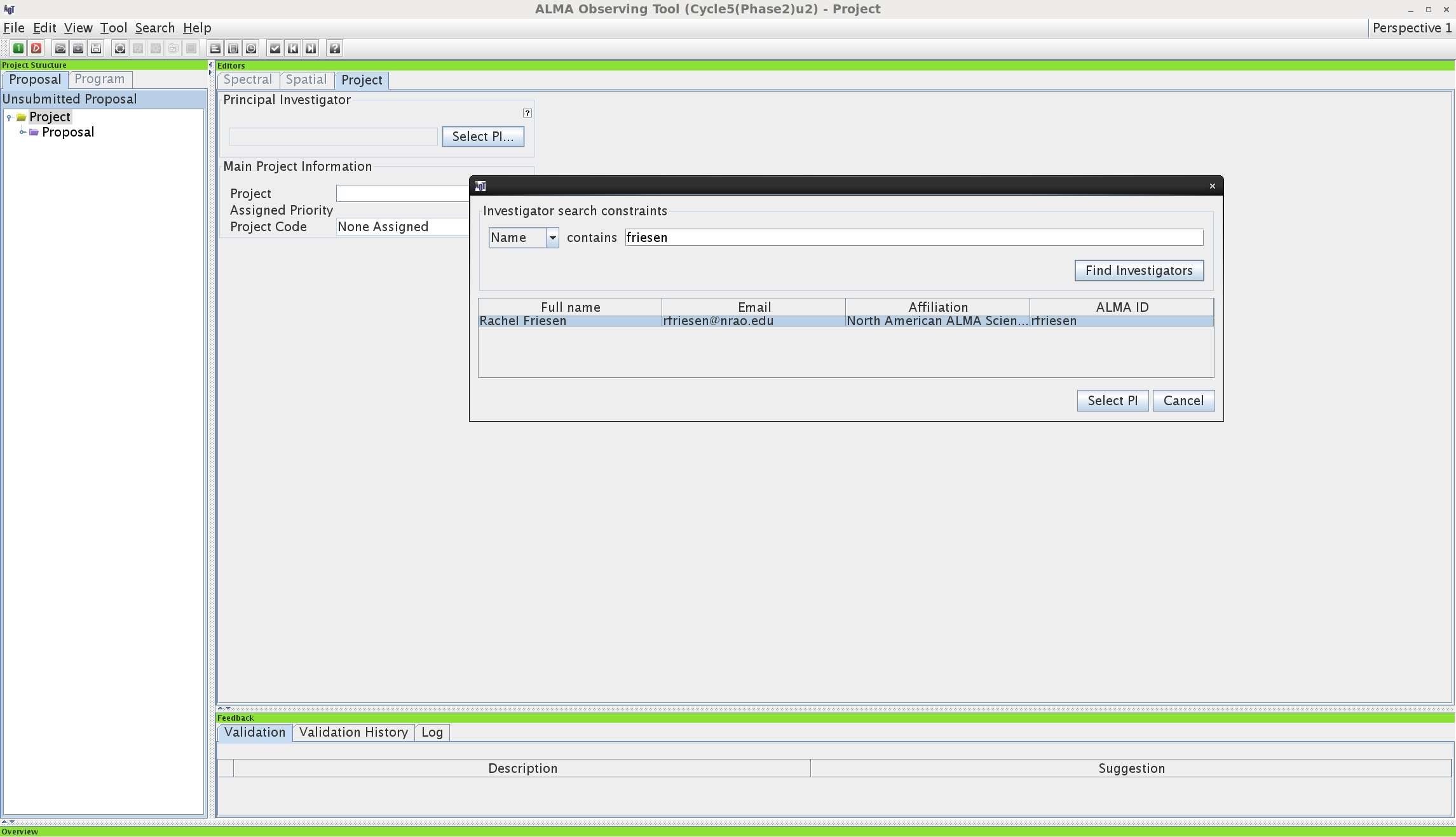
- click on 'Project' in the tree structure. If this were a real proposal, you would need to have an ALMA user ID, and so will all your co-investigators. If you don't already have an ALMA ID, you can sign up at the ALMA portal. For now, we will skip this step.
- next, click on 'Proposal' in the tree structure
- on the main panel, write some general information on the proposal (Title, Proposal Type, ...).
Create the science goals
An ALMA proposal is composed of one or several science goals (SG). In practice, each SG (or pseudo-SG) corresponds to observations obtained with a single receiver and correlator/receiver setup (except for spectral scan mode) of sources which are sufficiently nearby in the sky (~<10 degrees apart) to be observed with the same phase calibrator. However, a single science goal can be used with several arrays or configurations (for example, ACA and 12-m array, or extended 12-m and compact 12-m configurations). The telescope observation instructions (scheduling blocks or SBs) are produced based on the SGs inputs.
- Create one (or several) scientific goals by clicking on the 'target' button on the task bar of the OT ('New phase 1 science goal')
- In the project tree, click on the newly created SG. You will see that the SG is divided in 6 panels (General, Field, Spectral, Calibration, Control, Justification)
- In the 'General' panel of the SG, give a distinctive name to the science goal and a brief description - this well help you to keep track of your science goals, and your contact scientist if your proposal is accepted!
- The next sections will help you to fill each panel of the SG
<figure id="field_setup_resolve.png">
</figure>
Field panel (source definition)
In the tree structure click on the 'Field Setup' section of a SG
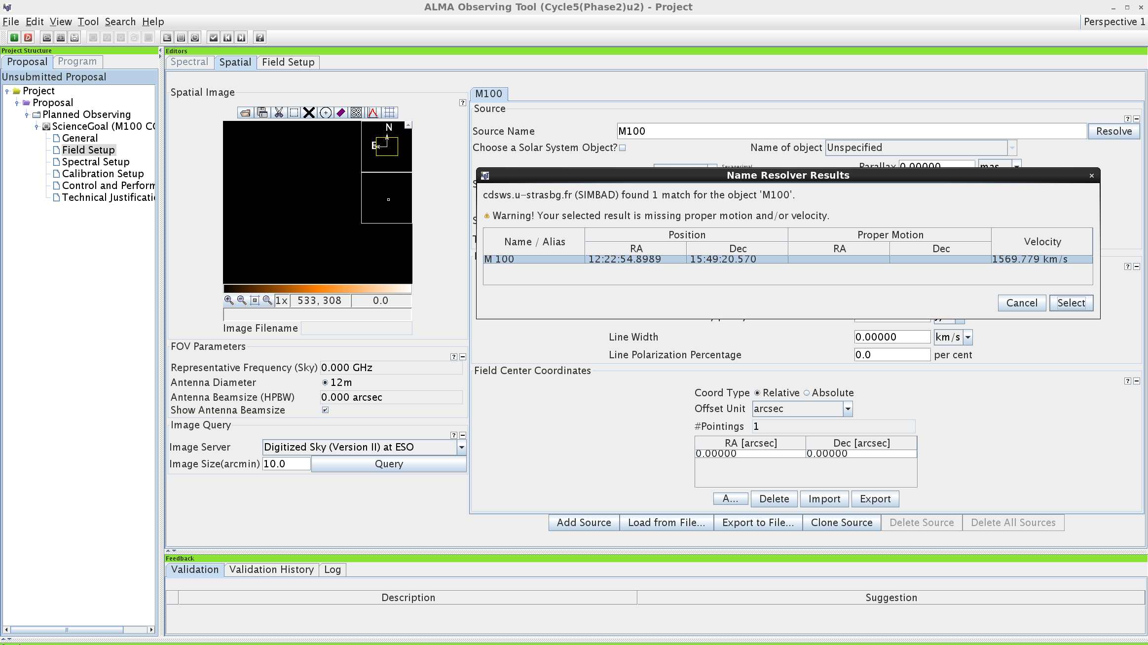
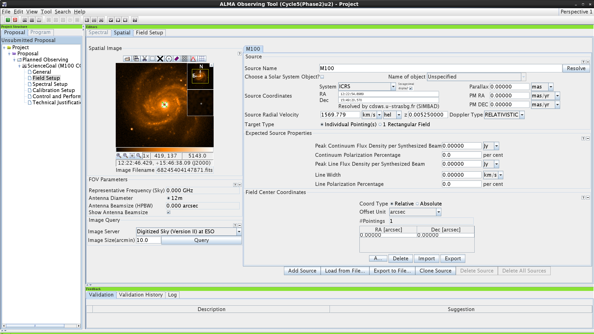
- In the Source section on this tab, define the name, coordinates and velocity (in km/s or z) of a source, as well as some expected properties
- For M100, we can take advantage of the OT's ability to resolve common source names! Type 'M100' into the 'Source Name' field and click on 'Resolve'
- For your own proposal, it is imperative that you check these values!
<figure id="field_setup_image_query.png">
</figure>
- Want to see what your source looks like in the Digitized Sky Survey? Do an image query! You could also use your own fits file if you have one (see the folder icon at the top left of the source image).
- Lastly, if your source size may extend beyond half of the primary beam of the telescope (which depends on the observing frequency), or if it is composed of several regions of interest which are more than half of the primary beam away from each other, you will need to observe multiple pointings within your source.
- Here, we want to map a large area of M100 - we will do this by clicking the 'rectangular field' option, which will tell the OT to calculate where the individual mosaic pointings should be. Note that this adds another set of inputs in the 'Rectangle' section on this tab! We want to map a square of 270" on a side, so set the 'p length' and 'q length' accordingly. The OT will suggest a number of pointings with the 12-m array, and - if necessary - a number of pointings with the 7m array. By default, the OT will calculate spacings based on Nyquist sampling, giving a constant noise level where beams overlap. You can change this, but make sure you know what you're doing!
<figure id="field_setup_correct_mosaic_size.png">
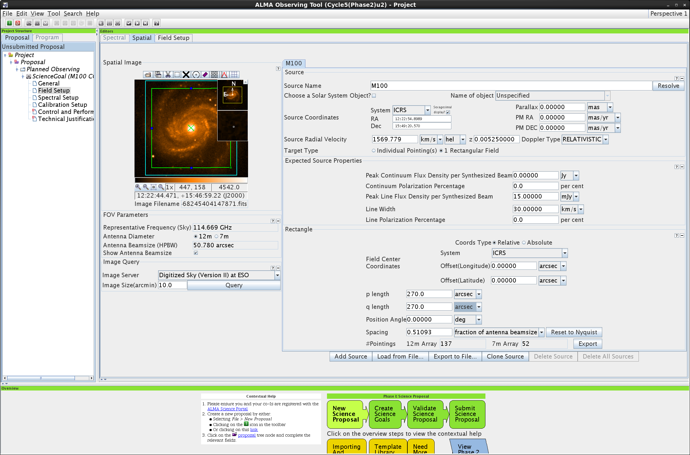
</figure>
In general for your own proposal, you may prefer to define yourself the coordinate of each pointing. Select 'individual pointings' on the 'target type' line. Add as many pointings as desired by clicking on 'Add' at the bottom of the 'Field Center coordinates' panel. You can define the coordinates of each pointing in RA/Dec or offsets from the coordinates defined above. By clicking 'custom mosaic', these pointings will be imaged as a single mosaic.
- Note that since we have not yet gone through the 'Spectral Setup' tab, the OT cannot yet calculate the pointings for the mosaic. We will return to this later.
- Next, fill in the Expected Source Properties section
- Note that the expected flux densities are defined 'per beam'. This corresponds to the flux encompassed in a resolution unit of the size of your requested angular resolution. For example, if you know that your source has a 4"-wide circular disk shape on the plane-of sky, emitting 1 Jy of continuum emission total, the peak flux density per beam of 0.4" will be 10 mJy.
- For M100, we are only interested in the line emission, so we can leave the continuum flux fields blank. We have already determined that the CO lines will be at least 15 mJy/beam in 10 km/s channels at 2" resolution. The line widths will actually be at least 30 km/s, so we will resolve the lines.
- If you want to add additional sources to the SG, click on 'Add Source' at the bottom of the panel. Here, we will stick with just one source.
- You can flip through the different defined sources by using the tabs at the top of the panel
<figure id="Spectral_line_picker.png">
</figure>
Spectral Setup panel (receiver and correlator setup)
<figure id="Spectral_setup_zoom_to_band.png">
</figure>
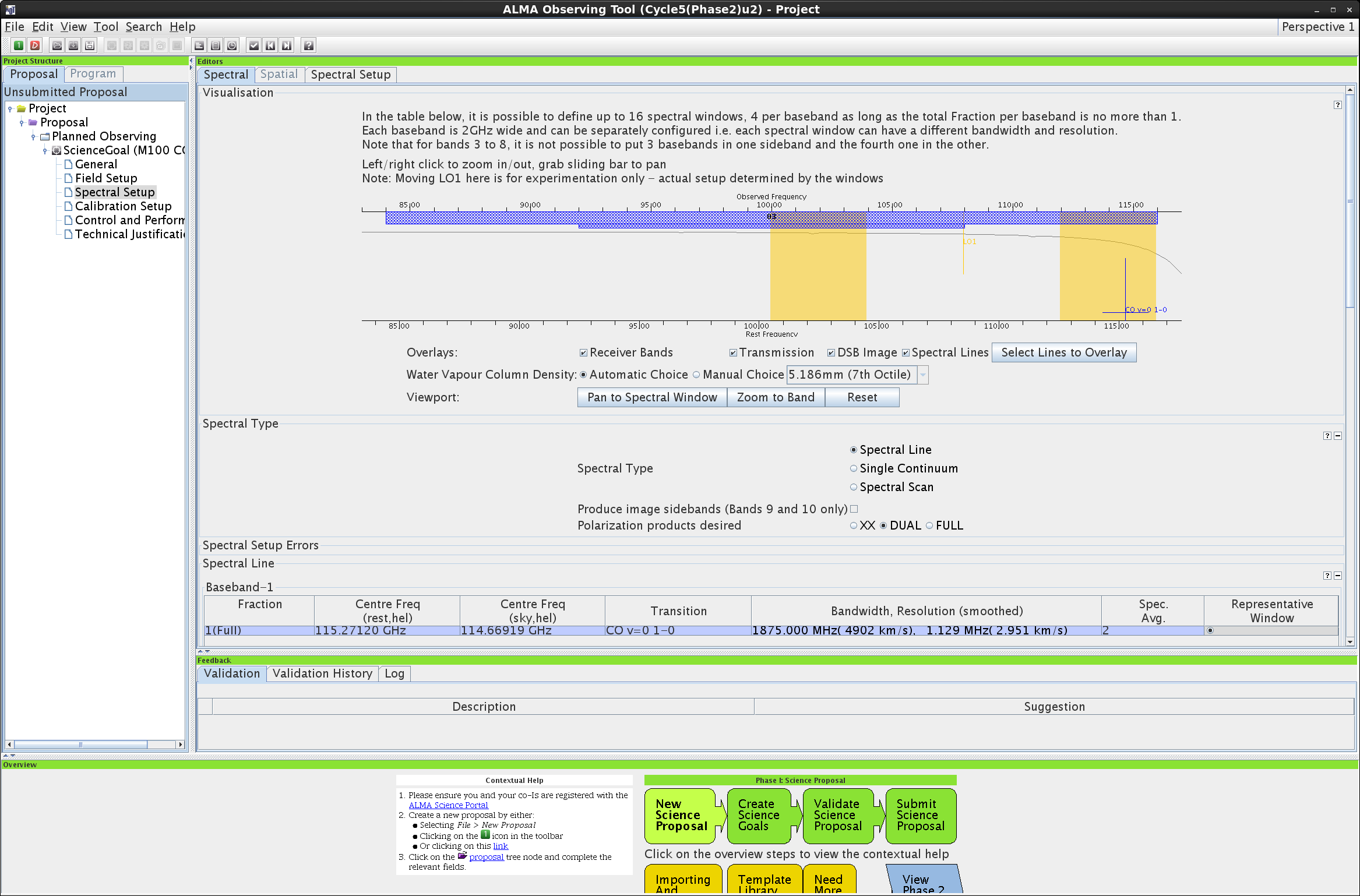
In the tree structure on the left panel in the display, click on the 'Spectral Setup' section of a SG. This will bring you to the spectral visualisation tab.
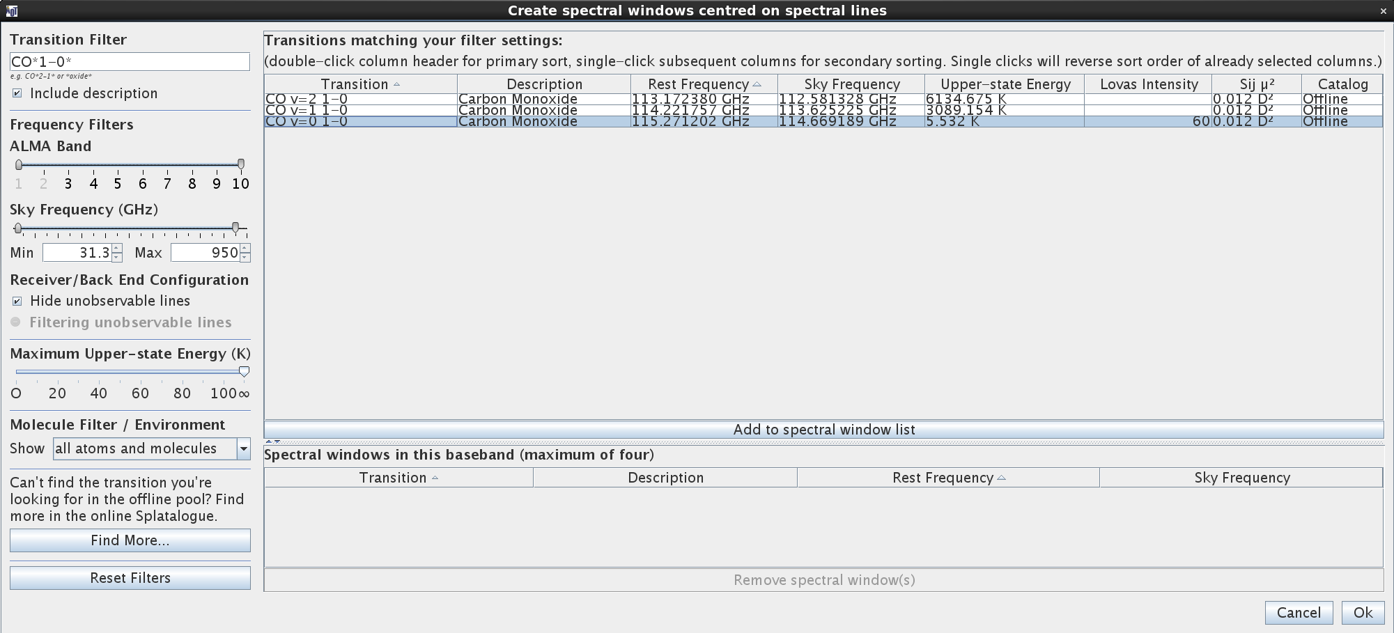
- We want to observe CO 1-0 toward M100. Scroll down to the Spectral Line section. Here, we can add spectral windows in each baseband. To do that in a given baseband, you can either:
- click on the 'Add spectral window centred on a spectral line' button below the baseband panel. This will pop up a window using the Splatalogue catalogue to show available lines. You can refine your line search by adding your preferred line to the 'Transition filter' box, or selecting on the left the desired ALMA band, the range of sky frequencies, or the maximum energy state of the transitions. Look for CO 1-0, highlight it and click on 'Add to spectral window list'. If you wanted, you could continue your line search and select up to 4 transitions. Selecting 'Hide unobservable lines' will remove any lines that fall outside of the frequency range available given your initial selection. You can also choose to search within a set of lines most commonly found in different astronomical environments in the 'Molecule filter/Environment' section. When you click on 'ok' (bottom right), a spectral window will be created for each of the selected transitions. Any unacceptable selection will be highlighted in red in the 'Spectral Setup Errors' box.
- You can also define spectral windows manually by clicking on the 'Add spectral window manually' button. An additional line appears above, in which you write the desired central frequency directly in either the 'rest' or 'sky' box.
- Define the spectral resolution/bandwidth and spectral smoothing of each spectral window. This is mainly driven by the expected width of the observed spectral lines, and how well you need to resolve them. Note that all spectral windows within a baseband must share the same resolution before smoothing. Because we only need 10 km/s spectral resolution for CO 1-0 toward M100, we will use the 1875 MHz width, 1.129 MHz (2.951 km/s) resolution option.
- Select which one of the spectral windows will define the representative frequency for which parameters such as noise, signal to noise and resolution are calculated.
- Once you have set up one or more spectral windows, you can look at the graphic view of your spectral setup plotted over the atmospheric absorption spectrum in the Visualisation section at the top of the panel. Use the 'Pan to Spectral Window' and 'Zoom to Band' buttons to look more closely at your setup. You can also zoom and pan in the window itself.
- Next, go back to the 'Field Setup' section in the OT. You can now actually see the mosaic positions chosen by the OT by clicking on the 'Show pointing positions' button above the source image (look for the icon of the box with four circles inside it). This is because the Nyquist spacing depends on the wavelength of the observations, which you have now included in the proposal. Ta da!
In general, if your project focuses on continuum only, you will probably want to maximize the observed bandwidth and use the low resolution-large bandwidth mode of the correlator (Time Division Mode or TDM). Define the receiver band corresponding to your chosen frequency, and you'll be given a default suggested frequency and a correlator setup (4 2-GHz wide spectral windows). You can change the average sky frequency (the corresponding rest frequency is shown below).

In the case of a line project, you will need to manually define each of the desired spectral windows within the four basebands. Each baseband encompasses at most 2 continuous GHz of the sky spectrum, and can be split in up to 4 spectral windows. There are several rules restricting how basebands and spectral windows within basebands can be setup with respect to each other.
Calibration Setup
<figure id="Control_and_performance_1.png">
</figure>
In this tab, you set whether you will use the system-defined calibration strategy, or another calibration strategy. Most projects will use the default system-defined calibration. This is what we will do here. You can read more about calibration strategies in the ALMA technical handbook. Choosing a non-default calibration option must be justified in the proposal and will make the proposed observations 'non-standard'.
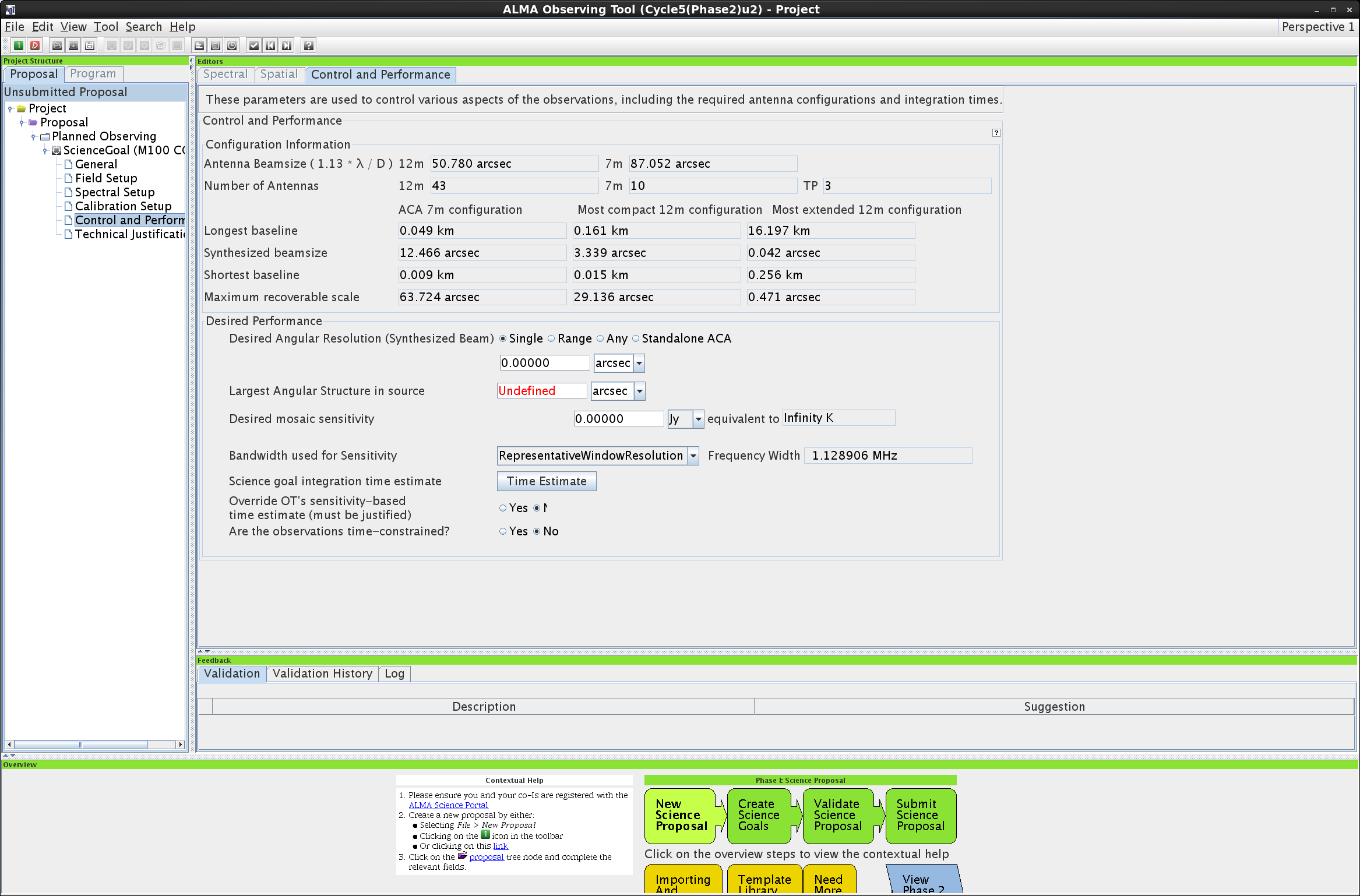
Control and performance panel
The signal to noise which you want to achieve drives the required sensitivity, which necessitates a certain amount of observing time to be reached. Determining the necessary sensitivity is (pretty) simple. You have an idea of the signal to noise you want on your detection (S/N ratio). You have an estimate of the flux density (signal) of the source per beam: for a continuum detection this is the peak continuum flux density. For a line detection, this is the peak flux density averaged over the lowest spectral resolution unit on which you want to achieve a detection (usually, the expected FWHM of the line). The sensitivity (noise) hence corresponds to the flux density per beam divided by the S/N ratio. If the SG includes different lines and continuum detections, each leading to different desired sensitivities, the desired sensitivity for the SG will be defined as the most stringent of these sensitivities.
In the tree structure on the left panel in the display, click on the 'Control and Performance' section of a SG. The top panel of this tab shows the array characteristics for the 12m and 7m arrays available given the frequency of your observations. You can see, for example, the allowed range in angular resolution given the most compact and most extended configurations of the 12m array for Cycle 6.
<figure id="Control_and_performance_2.png">
</figure>
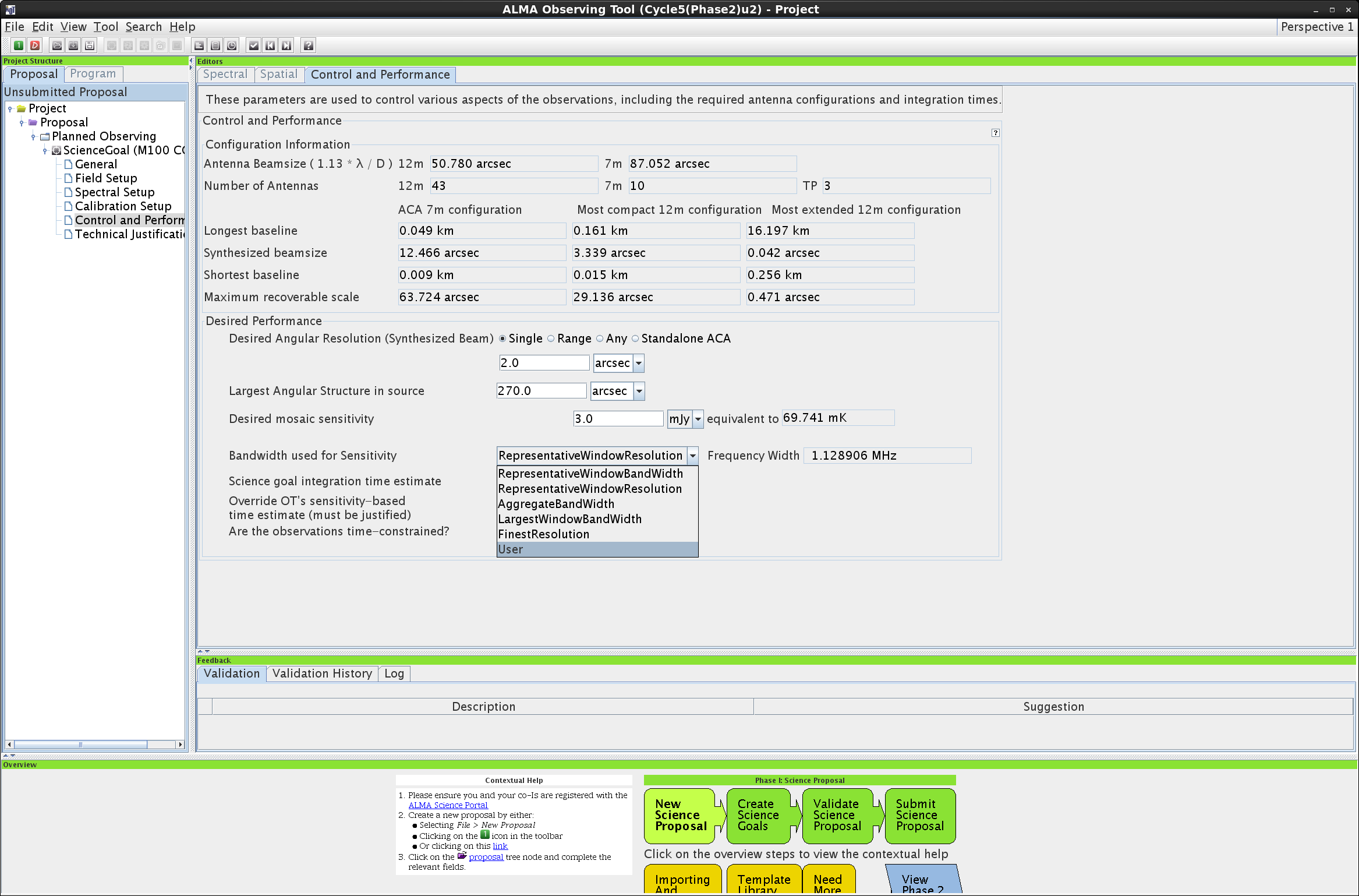
First, you need to set the imaging performance parameters which are necessary to perform your project
- Enter the desired angular resolution. This can either be a single value, a range, 'Any' (if you are observing a point source and the resolution is unimportant), or 'Standalone ACA' (a single value based on your observing frequency, not using ALMA's 12m array at all). For M100, we described above that we require 2" resolution.
- Enter the largest angular structure (LAS). For M100, we are setting the LAS to the size of the mosaic: 270". This value will strongly depend on your chosen source, and the OT uses it to determine whether your observations will require the ACA and/or the TP array to recover all the emission structure present toward your source.
- Write down your desired sensitivity in the correct units - for M100, we want a sensitivity of 3 mJy/beam in 10 km/s channels.
- Write the corresponding bandwidth. For a continuum project, this is the aggregate bandwidth over all spectral windows. For a line project like this one, this is the lowest spectral resolution unit on which you want to achieve the detection. Since we have based our sensitivity calculation on 10 km/s channels, we will change 'RepresentativeWindowResolution' to 'User', and set the Frequency Width to 10 km/s.
<figure id="TimeEstimate.png">
</figure>
Control and performance panel: observing time and arrays
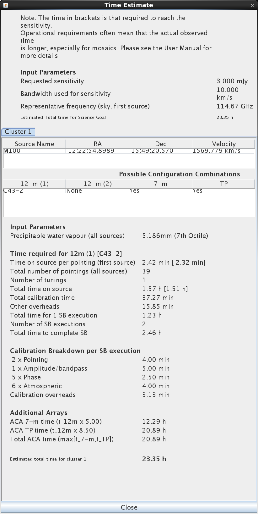
Click on 'Time Estimate'. You will obtain a breakdown of the estimated time to be spent on source and on calibrators, as well as which arrays and configurations are needed to perform the proposed measurement.
Depending on your desired angular resolution and the maximal characteristic scale which you want to image, the time estimator may indicate that a combination observation from different arrays or array configurations is needed. An extended configuration of the main array (the 12-m array, composed of at least 43 12-m antennas) may provide an excellent spatial resolution, but filter out large scales. This would be compensated by adding observations, not necessarily simultaneous, in a more compact configuration of the 12-m array, or observations by the ACA (Atacama Compact Array, composed of 9 7-m antennas). You will find more information to understand the concept of largest recoverable scale here.
For M100, the OT has calculated that we will need one configuration in the 12m array (C43-2, the second most compact configuration), plus ACA and TP observations (see the 'Additional Arrays' section near the bottom). You can how the OT has broken down the observations into time per pointing, number of pointings, number of executions, etc.
If you think that the final time estimate is too high with respect to what you could hope being awarded, there are many ways to drive it down. Remember that the observing time varies as the square of the sensitivity, so a small change in requested sensitivity can significantly change the time request.

* Increase the requested angular resolution. With a larger synthesized beam, the (resolved) sources' expected flux per beam increases. For a constant desired S/N ratio, the corresponding desired sensitivity will be increased.
* Decrease the size of the area to be mapped - hence decreasing the number of necessary pointings.
* Increase the spectral resolution unit for line detection.
* If possible, change the frequency for a frequency offering a better S/N ratio (often at the expense of spatial resolution)
* Eliminate scientific objectives which are too time-expensive
* In practice, the observations for a particular SG may be repeated over ''n'' number of executions to reach the desired sensitivity, as there is a maximum length of time for a single ALMA observation (including calibration time plus on-source time). In some cases, the total time request can be reduced significantly if the time needed to reach the required sensitivity is just enough to trigger an extra execution.

You may need several iterations to hone the most optimal observation parameters.
<figure id="Validate_look_for_errors.png">
</figure>
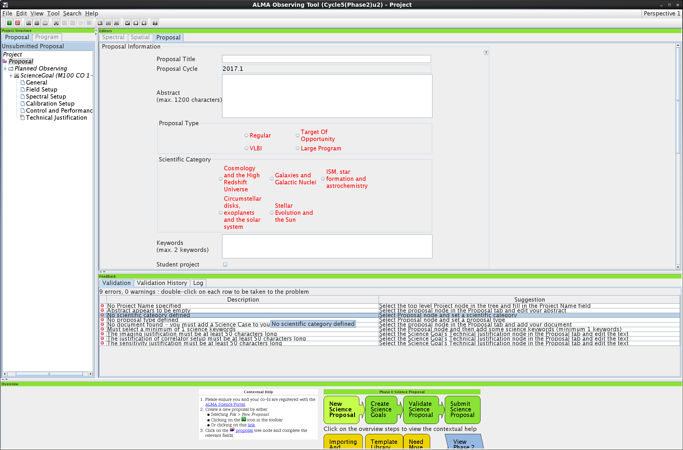
You have now defined most of your observational setup. To verify if all parameters are set in a correct way, run a proposal validation (check mark icon on the main task bar, or 'Validate' in the drop-down File menu). This will indicate if there are some errors in the proposal and parameters need to be changed. Clicking on a validation error will bring you to the tab where the issue lies.
If this was a real submission [INFORMATIONAL ONLY]
There are additional steps to undertake to transform a mock-up proposal into a real one. Those steps *should not be performed* during this exercise, but for your information only, here they are:
- justify your choices of observational parameters in the 'Technical Justification' tab
- attach a pdf of your scientific justification
- generate a pdf file of your proposal. In the Tool section at the top of the window, click on 'Generate a pdf'
- Submit it: In the File section at the top of the window, click on 'Submit'
Your own proposal
If you have time, go ahead and work through another Primer example, or start a proposal based on your own science idea! Follow the steps above to decide on your key science goals, identify line or continuum observations, determine the imaging requirements, and see how ALMA can help your science! If you would like to check out some ideas of what is possible with ALMA in Cycle 6 in order to get you started, look through the Primer, or check out the Did You Know page here.